

HOW TO WRITE SOFTWARE DETAIL DESIGN / SOFTWARE DESIGN DESCRIPTION (SDD) FOR AN EMBEDDED SYSTEM ACCORDING TO IEEE 29148 STANDARD
In previous article “How to write Software Requirements Specification (SRS) for an Embedded System according to IEEE 29148 Standard” we discussed in details the requirements analysis phase. In this article we will dive into the software design description phases and will record the design in SDD document according to IEEE 1016:2009 standard.
Software Detail Design View and Design Viewpoint
IEEE standard has organized design in the form of design views and design viewpoints. Design viewpoint is basically a perspective to address the software design description (SDD) and generally a good design requires more than one perspective. Design view is combination of design elements based on a particular design viewpoint.
Software Design Description (SDD)
First of all layout of SDD should be agreed upon between all stakeholders. One of the suggestive outline is given in Annex C of IEEE 1016:2009 standard. We will follow this outline and will explain each heading and put some example content under every heading.
Sample Project of Software detail design
In this article we are writing sample SDD for mission computer software of a generic aircraft. It is a very basic level SDD and you can tailor it for your specific project.
Introduction
Give a brief description of whole project whose software under consideration is a part. For example we are writing SDD for application software of a mission computer of an aircraft. It is a generic aircraft and main purpose of mission computer is to navigate the aircraft through waypoints according to the pilot inputs.
- Purpose
Define the purpose of the software under consideration. In our case this software has to take inputs from the pilot through throttle and display buttons, navigate the aircraft along the waypoints by moving the surfaces through servo motors and display flight data of every moment to the pilot.
- Scope
Name of the software is mission computer application software. It will get inputs from various sensors like Air Data Computer (ADC), Inertial Navigation Sensor (INS), Radar, etc. and will generate output for servos.
Software Detail Design Viewpoints
- Context Viewpoint
Context viewpoint basically depicts black box perspective of the software under consideration. Block diagram and use case diagram is the most appropriate to show context viewpoint.
In our example same diagrams as given in SRS will serve the purpose.
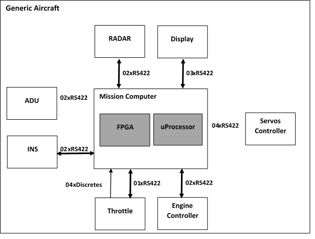
As you can see in the above diagram that software under consideration is shown gray. And all the products interacting with the software are shown with un-filled blocks. Communication protocol and number of channels are shown with arrows.
It is important to note that FPGA resides on the same host processor card. So separate SDD may be written for processor Application software and FPGA software because they are separate CSCIs. However they both can be covered in one SDD as well.
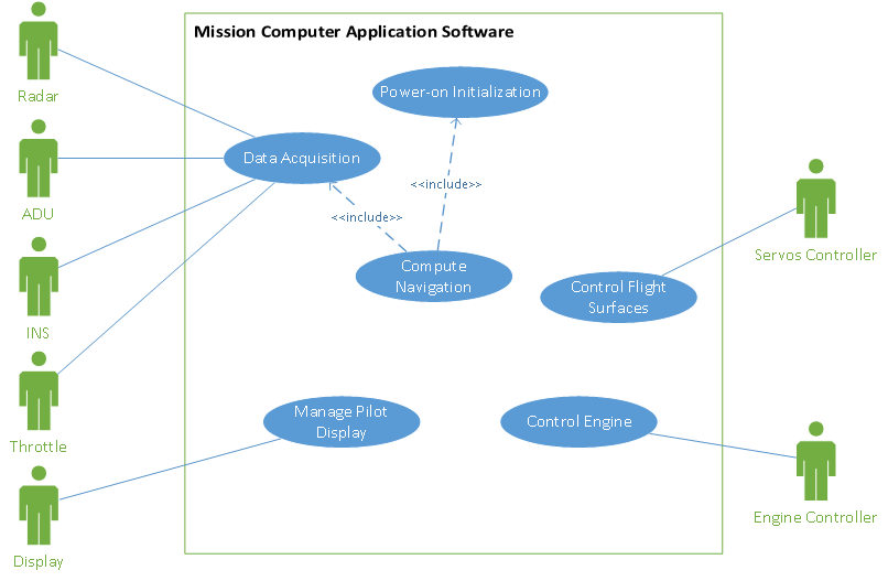
Use case diagram of main functions of the software is given below.
- Composition Viewpoint
Composition Viewpoint describes the way the software is structured into parts and establishes the roles of these parts.
Dividing the software into components produces reusability and better maintenance. One of the suggestion is to divide the software into layers. At least there can be two layers: Hardware Abstraction Layer (HAL) and Application Layer. HAL layer is dependent on underneath hardware and changes with the change of hardware. Whereas application layer implements business logic and should be independent of hardware changes.
For our example we have divided the software into two layers: HAL Layer and App Layer.
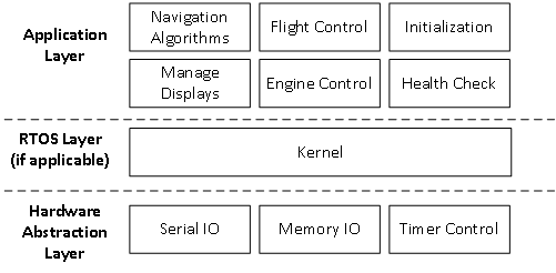
HAL layer constitutes of Serial IO, Memory Control and Timer Control. Serial IO can further be divided into serial in and serial out and even you can go up to the .c file level. For example you can define INS_Serial_In.c, INS_Serial_Out.c, ADC_Serial_In.c, ADC_Serial_Out.c, etc.
Similarly Application Layer consists of Initialization, Navigation Algorithm, Flight Control, Display Management, Engine Control, Health Check, etc. You can see that all these modules corresponds with cases of use given in Use Case Diagram.
- Information Viewpoint
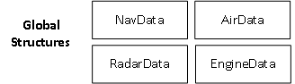
This viewpoint is related to data management and usage. In our example lot of data will be acquired from the sensors and this data will be used for business logic implementation in application layer and final outcome will be data again. We will define four C language data structures for transfer of data between layers. These four data structures are shown in the following diagram:
- State Dynamics Viewpoint
Main purpose of this viewpoint is to define internal states of the software. UML state diagrams are defined in this viewpoint and these are in more details than the diagrams given in SRS.
For our example one simplified state chart is given below:
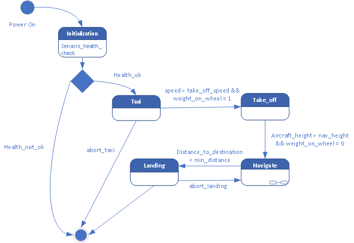
Note that there is sub-state chart symbol shown in Navigate state because it has second level state chart (states within state) and that state chart may have states ascend, descend, cruise, etc.
This state chart is simplified suggestive state chart whereas you can define states and state variables according to your system design needs.
There are many other viewpoints mentioned in the IEEE 1016:2009 standard e.g., logical viewpoint, dependency viewpoint, patterns viewpoint, interface viewpoint, structure viewpoint, interaction viewpoint and resources viewpoint. You can give details of the viewpoints whichever applicable on your system.